In the Box or In Situ?
The issue of quality control has been around since natural gas was first used as a fuel. For much of this time quality control has focused on moisture. Too much water vapour can cause corrosion of the pipeline and can form hydrates that cause blockages. In addition, gas that is too wet will not burn properly. Until fairly recently, most of the gas delivered to the end customer came from a single source, so the gas composition was rather stable. Therefore, assuming that there were no issues with any other components of the gas, it was only necessary to ensure that the moisture level was not too high.. By the 1930s the Bureau of Mines type tester had been developed, which enabled the accurate measurement of the water dew point of gas. This data could then be used to calculate the water content.
Although the Bureau of Mines instrument is still in use in many places, it is a portable but cumbersome device and is highly dependent on the skill of the operator. The tester was adequate and appropriate for its time, but since then technology has evolved greatly. A range of automatic and portable solutions for measuring how much water is in the gas have been developed, but the reason the old tester is still in use is that it utilises a chilled mirror and allows for visual confirmation of measurement results. Vympel offers a modern alternative to the dated Bureau of Mines testers. Its units incorporate up-to-date electronics, use a thermoelectric battery to cool the mirror and have a microscope for high resolution observation of the onset of condensation.
The challenge now is monitoring the hydrocarbon condensation temperature (HCT)1. Following the expansion of global natural gas infrastructure, it has become increasingly important to measure the HCT due to the increasing variability in gas composition as the sources of supply increase. Today, the gas in a pipeline is almost certainly a mixture of gases from a number of different sources, each of which has a unique composition profile.
While it may not be immediately apparent why variation in gas composition is something to be concerned about, a consideration of some of the main points that may arise will serve to bring the issue into focus. These include:
· Contractual obligations.
· Regulatory requirements.
· Technical problems.
· Operational monitoring. n Specific applications.
The contractual obligations are largely a financial issue. The price of natural gas sold in energy markets is determined by numerous factors including the HCT; a high HCT indicates the presence of heavier hydrocarbons in the gas at concentration levels that may impact the gas quality. Therefore, the HCT parameter is precisely defined in contracts negotiated between buyer and seller.
At the same time, increasingly stringent regulatory requirements are also being put forward for the HCT. This is seen as necessary in order to ensure that gas quality is maintained and to protect infrastructure and the rights of consumers.
The issue of technical problems refers to the consequences that arise when liquid phase hydrocarbons appear in pipeline gas. For example, the presence of hydrocarbon aerosols in the gas will have an erosive effect that may lead to the destruction of compressor blades and turbines.
In addition to preventing technical problems, it is also essential to monitor the operation of gas processing equipment to ensure that it is functioning properly. For example, it is important to monitor the HCT immediately downstream of heavy-hydrocarbon extraction equipment.
Finally, specific applications may require accurate HCT monitoring, including when gas is supplied to gas-fired turbines in power plants. Taking HCT measurements makes it possible to reduce the level of nitric oxide and thus prevent conditions that could lead to the formation of a reverse flare. Measurement of the HCT at commercial sites prior to delivery of natural gas to customers is another example of a specific application. This is conducted to meet the specifications of modern gas-fired appliances, which require gas of a certain quality to perform properly and operate safely.
Measuring condensation temperatures in natural gas
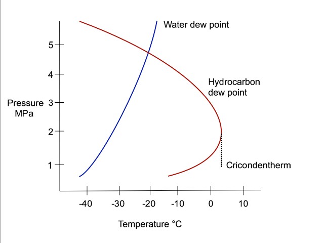
Figure 1 shows the phase diagrams for water and hydrocarbons of a typical gas mixture, relative to pressure and temperature. Perhaps the first point to note is that the condensation behaviour of water differs significantly from that of hydrocarbons. In recognition of this fact, and understanding that it is necessary to ensure that none of the components of the gas flowing through the pipeline condense into a liquid state, it is advisable to consider the relevance of pressure conditions when taking these measurements.

Figure 1. The relationship of the states of water (blue line) and hydrocarbons (red line) relative to pressure and temperature in a gaseous mixture.
In most situations, the water dew point can be measured at the operating pressure, matching the conditions in the pipeline. Indeed, this is often a contractual stipulation. On the other hand, due to the retrograde phase envelope of hydrocarbons, there is a ‘highest possible’ condensation temperature for each hydrocarbon. This temperature is known as the cricondentherm and it corresponds to a specific pressure. For optimal results it is important to measure the HCT at this pressure.
Another way of looking at this is to consider that measuring the HCT at the working pressure will not provide sufficient information to ensure that hydrocarbons will not condense into liquids at other pressures. For example, if the HCT is only measured at a pressure of 70 bar (pipeline pressure) and somewhere downstream of this measurement the pressure is reduced to 40 bar, condensation could occur unexpectedly.
The natural gas that is flowing through a pipeline is composed of multiple components, including a number of different hydrocarbons at varying concentration levels. Figure 2 shows the pressure–cricondentherm relationship for several typical gases mixtures. This illustrates the influence that heavy hydrocarbons can ultimately have on the cricondentherm of a given gas mixture, even when these heavy hydrocarbons are present in relatively low concentration levels.

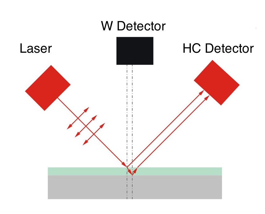
Figure 2. Schematic of the optical recording system used in the "CONG-Prima" series and "Hygrovision" series automatic analyzers manufactured by Vympel.
In order to adapt theoretical understanding of hydrocarbon behaviour to practical solutions, it has been necessary to standardise measurement practices. Studies conducted on different natural gases with various component compositions have shown that for all practical purposes, measuring the HCT at a standard pressure of
27 bar produces the best results. Therefore, the HCT is now typically measured at a pressure of 27 bar whenever possible.
Automatic HCT measurement
As already noted, gas composition fluctuation has increased the basic need for regular HCT measurement and, in order to truly meet the requirements of the modern system, these measurements must be made continuously. As most modern portable analysers are not designed for this type of operation, automatic devices have been developed.
In general, there is one approach to constructing a device for automatically measuring the HCT. The method employed in these devices is similar to that found in chilled-mirror hygrometers that are used to measure the water dew point automatically. These devices are also known as dew point analysers.
There are essentially three elements in such a device:
· A light source.
· A condensation surface (chilled mirror).
· A sensor.
The light source is directed onto the mirror in such a way that the light is reflected onto the sensor. For hygrometers used to measure the dew point of water, when droplets form on the mirror’s surface, the amount of light landing on the sensor is reduced. This reduction is registered and the dew point is established based on the temperature of the mirror when condensation occurs.
In the case of devices designed for measuring the HCT, the condensation behaviour of hydrocarbons requires certain modifications. As a result, the devices from various manufacturers have a number of significant differences, evidenced in the optical arrangements for registering condensates; the methods for processing the results obtained; and the structure and material used for the chilled mirror.
One of the earliest successful automatic HCT analysers was developed and patented by a US company. This device used a technology similar to that found in devices used for measuring the water dew point – with one essential change. In these analysers, an LED was used as a light source and the chilled mirror was made of metal that had an etched or non-reflective surface. This ‘roughing’ of the mirror’s surface was the essential adaptation for the hydrocarbon condensation behaviour, and differentiated these devices from water dew point analysers.
In this arrangement, the amount of light reaching the photo sensor when the mirror is dry is relatively low because of the mirror’s rough surface. As the mirror cools and hydrocarbons are deposited on the mirror’s surface, the light rays reaching the photo sensor increase due to the highly reflective nature of the hydrocarbon condensate film. In order to increase the sensitivity of this type of device, the signal waveform curve that is generated by the photo sensor is mathematically processed to clarify the point when condensation begins. This in turn allows for a more accurate identification of the temperature associated with the onset of condensation.
The next significant modification of the HCT analyser was developed by a competitor. This new design involved an alteration in the geometry of the etched mirror, forming it into a flat cone. In all other aspects the device is similar to the earlier design, but the change in the shape of the mirror allowed the developers to increase the sensitivity of the optical registration system. In this arrangement, as the hydrocarbons condense from reflective surfaces in the cavity of the cone, the light signal reaching the photo sensor is reduced to zero.
The most recent evolution of the basic light source, chilled mirror, and photo sensor arrangement has been developed by Vympel, based in the Russian Federation. The mirrors in these devices, which are made of a polished dielectric material, are both flat and highly reflective. This material enables the optical registration system to take advantage of the ‘total refraction’ phenomenon.
Total refraction is an effect that occurs when monochromatic (laser) light rays that are polarised in the longitudinal plane encounter the interface between dissimilar media at the Brewster’s angle. The Brewster’s angle for a given material is determined by its refractive index. The result of such an encounter is total refraction, or an absence of reflected light rays. The polished surface ensures that imperfections in the mirror do not result in unwanted light 'noise' reaching the photo sensor prior to condensation.
In the company's HCT analysers, when the mirror is dry or free of condensates, no light reaches the photo sensor. The condensation of a thin hydrocarbon film means that the light from the laser is no longer encountering the dielectric mirror but a different substance with a different refraction index. As a result, some of the light is reflected onto the photo sensors. But the hydrocarbons condensing onto the mirror are semitransparent, and this fact gives rise to an interference effect due to the appearance of two distinct light signals.
Figure 3 illustrates how this dual signal arises as the light rays from the laser are bifurcated when they encounter the hydrocarbon film. In other words, a portion of the light rays is reflected to the photo sensor and another portion is refracted through the film to meet the hydrocarbon film/mirror interface. At this point, however, the angle of incidence at the interface has been altered by the aforementioned refraction, so these light rays no longer reach the mirror at the Brewster’s angle. This results in a portion of these light rays also being reflected onto the sensor. However, as this second set of light rays has travelled further than the first, the light signals are out of phase and thus create a pattern of interference. This type of optical system makes it possible to register a film that is only 10 nm thick. This level of sensitivity is a fourfold improvement on the best of the earlier designs.

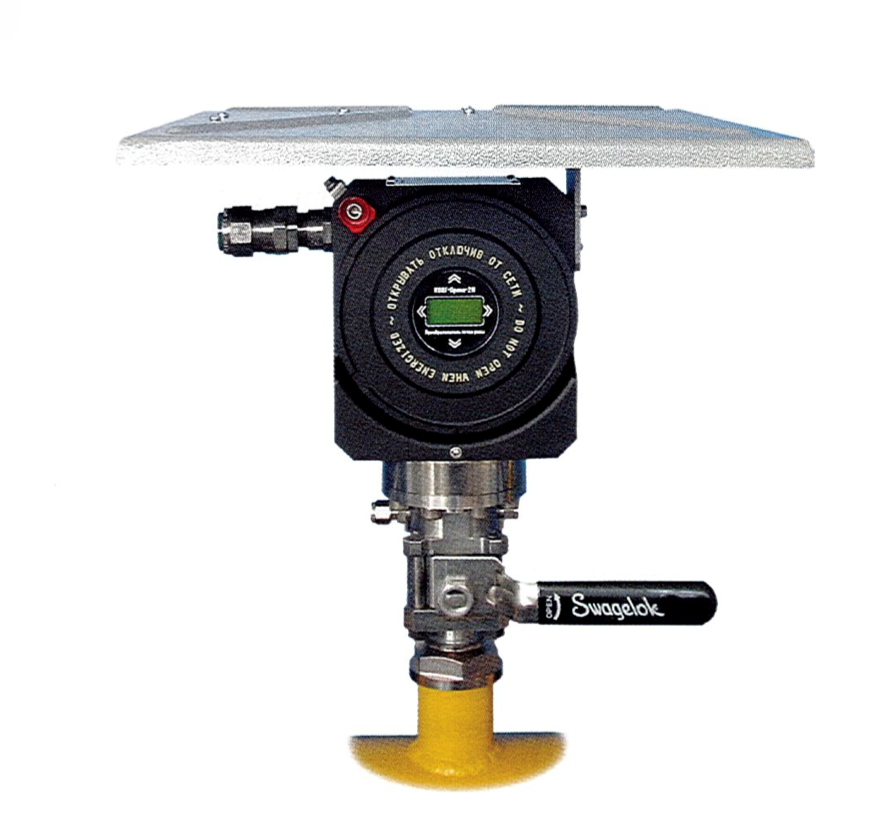
Figure. 3 CONG-Prima 2M dew point analyzer installed in situ directly on the pipeline and outfitted with a sunshade.
It is also worth noting that the principles upon which the Vympel analysers are based facilitate measuring the water dew point as well as the HCT (though not simultaneously). Water condensation forms tiny droplets instead of a reflective film, so the placement of additional photo sensors in the measurement cell allows the analysers to take advantage of this difference in condensation behaviour. When water droplets form they cause the laser’s light rays to scatter and this scattering is registered by the additional photo sensors as a signal that is distinct from that caused by hydrocarbon condensates. The earlier technologies are not able to measure both values.
Installation of automatic HCT analysers
The need for continuous quality control measurements at various points in the natural gas delivery chain has resulted in the development and installation of a number of analytical devices, including HCT analysers, water dew point hygrometers, oxygen sensors, H2S analysers, CO2 sensors and gas chromatographs.
In most cases, these devices are all placed inside of an enclosure on-site at a natural gas facility. The reasons for this are several, including the need to protect sensitive instruments from the effects of the weather and direct sun exposure. In addition, an enclosure can provide a stable ambient environment within which measurements and analysis can take place under optimal conditions. In fact, some devices require this type of stable condition to operate correctly. Even if there is not a full enclosure, it is almost universally necessary to have a wall or frame of some kind upon which to mount the various devices.
Moreover, an enclosure provides a location for the system that is often necessary to prepare the gas for analysis. This preparation system usually includes filtration, pressure adjustment and flow control. Depending on the specific application, it may be absolutely critical to filter the gas in order to avoid fouling the analysis equipment. At the same time, different types of equipment have different requirements in terms of flowrate and pressure conditions in order to preform reliably and provide accurate measurement results.
That being said, locating the quality control equipment in an enclosure is not always the most desirable solution. For example, if only one or two devices are needed, the placement of an entire enclosure adds undo expense. Also, it is often the case that the sample gas line connecting the pipeline to the enclosure is several meters long. This can compromise the sample gas before it reaches the analysers, as the sample line may become contaminated with moisture or heavy hydrocarbons. On the other hand, if measurements can be made directly on the pipeline, those results will most accurately reflect the real conditions in the pipeline.
Although for most types of instruments, the options for direct installation on the pipeline (in situ installation), are extremely limited or even nonexistent, Vympel's CONG-Prima 2M (CP2M) can be installed in this manner.
This CP2M series of automatic analysers are small and self-contained, so can fit directly onto a sampling probe. The measurement cell of the CP2M is connected directly to the sample gas line in all installations. The device's small size and simple configuration provide flexibility, allowing for different installation arrangements.
In the case of an in situ installation, the device is mounted directly onto a specially designed sampling probe on the pipeline (Figure 4). This solution is best suited to clean, dry gas where additional filtration is not required. However, if in situ installation is determined to be the best option, even if the gas may need some additional filtration, a specially designed ‘Genie’ filter can be mounted between the sampling probe and the analyser. There are also accessories available to protect the CP2M from the sun and weather, as these factors may still to present a challenge. Pressure is also a factor in determining whether or not an in situ installation is appropriate, as the introduction of a change in pressure will necessarily require a slightly more complex system.
Conclusion
The evolving gas infrastructure presents new challenges and new opportunities. One of the solutions to those challenges is the development of devices that can be installed directly on the pipeline. As is outlined here, one such device is already available for taking HCT measurements. Although it is not the right solution for every situation, an in situ option for installing an HCT analyser means that effective continuous automatic quality control measurements can be taken at locations where previously it was not possible or was not cost effective.
Note
1. The HCT is also referred to as the hydrocarbon dew point. There is general agreement that this terminology is less than desirable, as the HCT is a function of many different hydrocarbon components, each of which has a different condensation temperature, whereas the condensation temperature of water or ‘dew point’ deals with a single component.
