Mirror Mirror on the Wall
All analysers that are designed to directly measure the hydrocarbon dew point are based on the chilled-mirror paradigm in which a surface adjacent to the gas is cooled until a hydrocarbon component of the gas changes phase to liquid, forming a condensate on the cooled surface (chilled mirror). The temperature at which this occurs is registered as the hydrocarbon condensation temperature (HCT).
One of the challenges to accurately measuring HCT is how to calibrate the analyser. Unlike the water dew point, where the measurement is of a single gaseous component that displays a predictable behaviour, HCT, as mentioned previously, is the temperature at which the first hydrocarbon condensate begins to appear, which involves not one but many components, each of which has slightly different condensation behaviour. Moreover, the interaction of these components cannot be accurately predicted. In addition, hydrocarbon components are present in very different concentrations, from the lightest hydrocarbon, methane, which may constitute as much as 97 – 98% of the gas, to much heavier hydrocarbons, such as nonanes and decanes, which may be present in only trace amounts. These proportions can fluctuate depending on several factors, including changes in the gas source and the mixture of gas from more than one source. The relative presence and the interactions of these components with one another influence the temperature at which the first condensate begins to form.

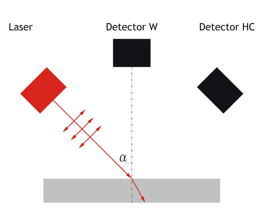
Figure 1. When a polarised laser encounters a dielectric material (in this case the surface of the chilled mirror) at a specific angle of incidence, known as the Brewster angle, the result is total refraction of the light signal.

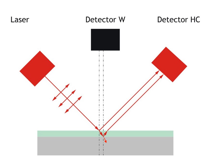
Figure 2. When a polarised laser encounters a hydrocarbon film on the surface of the chilled mirror (dielectric), the result is a bifurcation of the laser light signal and a disruption of total refraction. As a result, the two light signals reaching the photo sensor are out of phase with one another.
Unsurprisingly, heavier hydrocarbons tend to condense before lighter ones. The presence of these heavier components can have an outsized impact on HCT and may result in misleading measurement results. Consequently, determining HCT is dependent on the sensitivity of the technology used to register the condensate formation. A highly sensitive instrument may well be able to register even the trace amounts of heavy hydrocarbon condensate at a temperature much higher than that measurable with a less sensitive instrument, which can only register larger amounts of condensation from lighter components that are present in larger quantities.
The propane problem
The traditional standard method of calibration, which uses high-purity propane as a calibration gas, has become increasingly unsatisfactory. New generations of analysers have resulted in significant differences in condensation registration sensitivity between analysers. The use of a single-component gas, such as propane, to calibrate one of these instruments no longer provides a useful baseline for calibration. The issue with propane is its steep condensation gradient. This means that over a very small temperature range (measured in tenths of a degree) a significant amount of propane will precipitate out of the gas phase. This is in comparison to the condensation gradient for a multicomponent gas, such as natural gas, in which the rate of precipitation is much slower and spread over a much wider temperature range.
The main reasons for the continued use of propane are its almost universal availability and its well-known condensation behaviour. Unfortunately, the steep condensation gradient of propane means that analysers with drastically different sensitivity can be equally well-calibrated to the calibration gas (propane), but will produce different results when measuring the actual natural gas they intend to monitor.
Alternative calibration
There are several remedies for the propane problem, including the use of a multicomponent calibration gas that has been specifically produced to simulate real conditions. The hurdle in this case is a lack of wide availability and increased expense.
Another alternative is to redefine the calibration specification, moving away from simply registering the first condensation an analyser can identify to registering the temperature that corresponds to a given amount of condensate. Recently, this approach was explored in the GERG Project l.64, carried out at Open Grid Europe in Essen, Germany. The calibration standard used for this project was 5 mg/m3. In other words, the analysers involved were calibrated to register HCT that corresponded to 5 mg/m3 of condensate on the chilled mirror. The advantage of this approach is that it minimizes the impact of differing instrument sensitivity.
In order to establish a 5 mg/m3 baseline temperature, a gas is subjected to gravimetric analysis in accordance with DIN EN ISO 6570. The gas used can be a specially prepared calibration gas or it can be the actual pipeline gas that will be continuously monitored - in fact, the latter is to be preferred. Gravimetric analysis is employed to establish the temperature that correlates to 5 mg/m3 of potential hydrocarbon liquid content (PHLC) in the gas. Once this temperature is identified, the analysers can be set up to report HCT based on this baseline.
This calibration method does not involve a simple shift of the calibration curve of a given instrument. Rather, the sensitivity of the registration system is actually adjusted. In some devices, the sensitivity is reduced, thereby increasing the threshold of condensate registration, while in other devices, sensitivity is increased, thereby lowering the threshold. In some cases, this involves the introduction of algorithms to compensate for limitations in sensitivity. As a result of this calibration approach, differences in technology and sensitivity can be largely mitigated, leading to more satisfactory results in producing comparable measurements. In the GERG Project, for. example, after calibrating the analysers to the 5 mg/m3 standard, a measurement discrepancy was obtained in the 3 - 4° C range, as opposed to a discrepancy in measurement results of around 24 °C using traditional calibration.
However, this calibration method also has its limitations. One of the main factors is that calibration is best carried out based on the gas with a component composition like that of the gas being monitored. If the composition of the gas changes, it will likely be necessary to re-calibrate the sensitivity of the hygrometers as well, in order to ensure that the correlation of the analyzers’ sensitivity to the 5 mg/m3 remains consistent. In addition, during that period of time in which calibration is carried out, often in the range of 6 - 8 hrs, the composition of the gas should remain more stable than usual.
Considering these points, using this calibration technique presents additional complications and it is not always possible to fulfil all the conditions for successful implementation of this approach at real-world natural gas facilities. Even so, the
5 mg/m3 concept is essentially quite sound, and it offers the possibility for improved quality management. The challenge, then, is to develop an HCT analyser with a built-in functionality that would maintain the 5 mg/m3 calibration.
Improving analysis
Taking into account the benefits and difficulties inherent in gravimetric calibration, one manufacturer of on line hygrometers, SPA Vympel LLC, began development of an HCT analyser with built-in functionality. The task was to develop an analyser that would periodically, automatically adjust the sensitivity of the condensate registration system in order to maintain the baseline standard of 5 mg/m3 of PHLC.
It became possible to pursue this development because of the underlying technology used in the company's automatic analysers. This technology is based on the phenomenon of total refraction, which results when the light from a polarised laser strikes a dielectric surface at a specific angle. This angle is called the Brewster angle and is dependent on the refractive index of the material. When a polarised laser strikes a dielectric surface at the Brewster angle, the result is that virtually all the light is refracted into the material, essentially eliminating all ref1ected light. This effect is known as total refraction. In the case of an automatic hygrometer, the mirror is made of the dielectric material. In this way, using a polarised laser as a light source, the light that would normally be ref1ected onto a photosensor is captured through total refraction, and the analyser registers this lack of light arriving at the sensor as an absence of condensate (Figure 1).
As the mirror is cooled and hydrocarbon condensates begin to collect, a ref1ective film is formed. This film has a different refractive index from the mirror, so not all of the light from the laser is refracted and some of it is immediately ref1ected onto the photosensor. But the process does not stop there. Some of the light from the laser striking the condensation is refracted and passes through the film to encounter the mirror. But now the angle at which this light hits the mirror is no longer the Brewster angle, so some of the light is ref1ected from the mirror's surface and eventually arrives at the photosensor (Figure 2). As a result of this sequence of events, two separate laser signals reach the photosensor, and because one of these signals has travelled farther than the other, they are out of phase. This generates a pattern of interference that is analysed to reveal not only the presence of hydrocarbon condensates with a high degree of sensitivity, but also information about the thickness of the film.
The sensitivity available using this method of measurement makes it possible to record the formation of a film of hydrocarbons with only a slight amount of ref1ected signal. Using a laser with a wavelength of 670 nm as the light source, this interferometric method allows the analyser to register a film of hydrocarbon condensation with a thickness of only 5 nm.
PHLC detection
After further research and development, this technology suggested a method for determining the amount of PHLC when the gas is cooled to a temperature below the actual HCT.
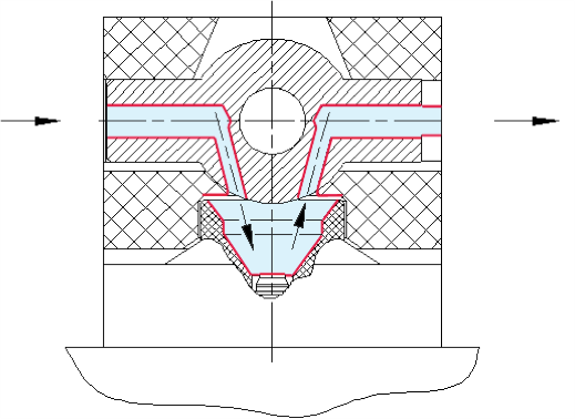
In order to take advantage of this potential, a device was developed that makes possible the simulation of conditions that would result in the condensation of hydrocarbons in the pipeline. Figure 3 shows a schematic representation of this device, including a measuring chamber with a cooled mirror and a two-position ball valve .
With the ball valve in position one, the gas flow is directed through the measuring chamber, where it passes across the surface of the chilled mirror. With the ball valve in position two, the gas flow is directed through an alternate channel, and the volume of gas adjacent to the mirror is cut off from the gas flow and a sealed volume with a known size is created, As a result of the addition of the ball valve device, it became possible for the analyser to make two different types of measurement. With the ball valve in position one, HCT can be measured as normal, and with the ball valve in position two, the amount of hydrocarbon liquid deposited on the chilled mirror can be measured. This measurement is based on the area of the mirror's surface, the average density of the hydrocarbon liquids, the thickness of the condensation fi Im, and the volume of the sealed space above the mirror.
In execution, this second measurement is carried out by cooling the surface of the mirror to a temperature below the previously measured HCT (as measured with the ball valve in position one) until a certain thickness of condensate film is formed. Knowing the thickness of the film, the area of the chilled mirror and the average density of the condensate, the mass (m) of the condensed liquid is calculated as follows:
m = S×h×ρ = 4.2×10⁻⁶×h
where:
· S (the area of the cooled mirror) = 6 × 10⁻¹ m-2 .
· ρ (the averaged density of the hydrocarbon liquid) = 700 kg/m3.
· h is the measured thickness of the layer of hydrocarbon condensate on the mirror. This number is determined using the value of the measured photocurrent from the photodetector.
Knowing the mass of the hydrocarbon condensate on the mirror and the size of the sealed volume of gas above the mirror, it is possible to calculate a value for the amount of hydrocarbon liquid (W) that is deposited on the mirror at a given temperature using the following formula:
W = m/VK
where:
· m is the mass of the hydrocarbon condensate, calculated using the first formula.
· VK (the sealed volume of the measuring chamber) = 2.8 x 10⁻⁶ m3

Figure 3. The ball valve directing the gas stream onto the surface of the mirror for normal measurements (left); the ball valve directing the gas stream to bypass the mirror while sealing the measurement chamber to create a closed space for recalibration measurements (right).
Using the above formulae, based on a given liquid
33 density of 700 kg/m , and PHLC dropout equalling 5 mg/m
of hydrocarbon at the cricondentherm pressure of 27 bar, the condensate layer on the mirror’s surface will have a thickness of 90 nm. When the ball valve is in position two, it is possible to measure the temperature corresponding to
3
a PHLC dropout of 5 mg/m . Knowing the temperature
corresponding to 5 mg/m3 of PHLC dropout, it is not difficult to introduce a sensitivity correction into the main loop of the algorithm for measuring HCT, and in this way automatically recalibrate the analyser.
Conclusion
The technology of nano-measurements using laser-based interferometric analysis, as is used in the CONG-Prima and Hygrovision series devices from Vympel, has led to the development of a fundamentally new concept in the automatic measurement of the specific amount of hydrocarbon condensate precipitating out of natural gas at a temperatures below HCT. It is this direct measurement of a previously inaccessible physical parameter that presents a fundamental paradigm shift in gas quality control.
In addition, the possibilities presented by studying the dynamics of hydrocarbon condensation in the registration of hydrocarbon film thickness and the amount of condensate deposited on the chilled mirror suggest that laser-based interferometry can evolve to become a new scientific tool used to study the thermodynamics and kinetics of liquid condensing from the gas phase.
However, it should be noted that, currently, the following issues remain unresolved: calibration of HCT analysers using propane will continue to be widely used until such time as better methods are more universally and economically available, and field technicians are trained in those methods; and calibration using the gravimetric method is not universally recognised because of the lack of means for reproduction and reference standards, and the lack of regulatory guidelines.
Bibliography:
1. DEREVYAGIN, A., SELEZNEV, S., STEPANOV, A., AGALTSOV, A.,
and ISTOMIN, V., ‘A New Approach for Measuring Water and Heavy Hydrocarbon Dew Points of Natural Gases by Using a Three-Channel Laser Interferometer’, Materials of the 23rd World Gas Conference, Amsterdam (2006), report no. 99.16.
2. WOLF, M., ‘Installation, calibration and validation guidelines for online hydrocarbon dew point analysers – GERG PC1 / Project 1.64 / Phase 2’, International Gas Union Research Conference, Copenhagen (2014).
