Sampling Solutions
-
A.M. Derevyagin, et al., SPA Vympel, Russia, and Paul Lyon, Vympel GmbH, Germany, explore new approaches to gas sample treatment for analytical measurements.
An essential aspect of the modern natural gas delivery chain is quality control. Gas quality is monitored at many points in this chain – at gas processing and storage facilities, gas blending installations, custody transfer points, international borders, and pumping stations, to name a few.
Quality monitoring requires a number of different analysers, each one dedicated to measuring a specific component or parameter of the gas. Each of these instruments has different requirements with regard to gas preparation before analysis. One critical aspect of gas preparation is purification.
A gas sample almost always contains a variety of contaminants. These can be mechanical in nature (scale, sand, hematite dust, etc.) or liquid (glycols, oils, excessive water, etc). The presence of impurities can distort measurement results and, in some cases, prevent measurements from being taken at all.
The sources of contamination are manifold. Natural gas is a veritable witches brew of contaminants as it comes out of the ground. Even after the gas is processed and injected into the transport system, impurities may be reintroduced. The equipment needed to maintain pipeline pressures can be a source of significant amounts of turbine or compressor oils.
These oils can accumulate on surfaces inside analysers and will ultimately lead to a significant reduction in an instrument’s sensitivity. Similarly, residual glycols that are used for gas dehydration – usually diethylene glycol (DEG) – act in much the same way as compressor oils. Glycol aerosol that comes into contact and condenses onto the inner surfaces of an analyser forms a film, which over time impairs the sensitivity of the instrument. Unsurprisingly, glycol contamination is especially great where hygrometers are installed to monitor the humidity of gas as it exits glycol dehydration equipment. This type of dryer is a common solution installed at gas treatment plants and underground gas storage facilities.
A similar challenge is presented by gas components that are not necessarily contaminants. For example, the gas produced by developed gas condensate fields usually contains more than trace amounts of pentane, heptane, hexane and other hydrocarbons. These are usually denoted as C5+ hydrocarbons or heavy hydrocarbons (HH), regardless of whether they are present in a gaseous or a liquid state. When heavy hydrocarbons condense, they have low surface tension and easily form films on the surfaces of many materials, including the sorbent agents within sorption sensors and the mirrors of condensation hygrometers. The heaviest hydrocarbons, known as paraffins, form a solid film that over time begins to ‘encapsulate’ the sensing element, isolating it from the gas altogether.
Humidity metering can also be affected by ‘sharp spatial discontinuity’, in other words, the absolute and relative concentrations of impurities can change significantly throughout the process chain. For example, the amount of DEG present in the gas immediately downstream from the glycol dehydration section is a thousand times higher than it is in commercial grade gas, thus a hygrometer that can operate reliably on the metering node at the end of the gas pipeline may not be suited for applications at a gas treatment plant.
Impurities may also appear unexpectedly. For example, dehydration of a section of pipeline will cause a cloud of methanol vapour to pass through the whole system, downstream of the dehydration point. This may cause the failure of a previously reliable hygrometer.
As an illustration of the ever-increasing complexity of monitoring and diagnostic tasks, an issue that has recently emerged as a particular challenge is measuring the humidity level of oil-associated gas that has a methane content below 60%. If propane (C3) and butane (C4) hydrocarbons condense before water vapour does, it is extremely difficult to measure the water dew point (WDP) temperature using condensation hygrometers. When these hydrocarbons condense, they form three dimensional droplets on the mirror. The optical systems found in modern hygrometers have great difficulty in differentiating these droplets from those of water condensation. Under these conditions, only an experienced operator can measure the dew point manually using a visual hygrometer. However, this manual method is not compliant with official standards, such as GOST R 53763-2009 in Russia. It is also important to note that for these types of ‘oil gases’, WDP measurements made by sorption type hygrometers can be just as doubtful.
In light of the challenges presented by gas composition, including impurities, what has become increasingly clear is the importance of a thorough study and understanding of gas preparation for analysis.
Filtration is, of course, a key aspect of gas preparation. But, as has already been seen, specific conditions require specific filter solutions. After all, a simple membrane is of little use when the problem is the early condensation of heavy hydrocarbons.
In this article, three specific filter solutions that have been developed by SPA Vympel will be examined.
Measuring WDP in gases
During a measurement cycle, if, as the mirror is cooled, water condensation occurs before hydrocarbon condensation, chilled mirror hygrometers can produce reliable measurements of the WDP. However, if the gas contains high concentrations of propane, butane, pentane and other heavier hydrocarbons, these components will condense first. In most of these cases, the hydrocarbon condensation temperature (HCT) is 3 - 10 °C higher than the WDP temperature.
Liquid water and liquid state heavier hydrocarbons have similar optical properties, a situation that hinders visual measurements made by operators (i.e. in the manual mode) and creates noise in the automatic measurement mode. The solution to this problem involves decreasing the HCT before measuring the WDP.
Lowering the HCT requires the removal of a sufficient number of HH molecules from the gas to reach the desired condensation temperature range, however, until now, this has been easier said than done.
In response to this issue, Vympel developed two types of filters: a carbon type filter (Glycosorb) and an oil type filter, that have been designed to remove hydrocarbons and glycol vapors from natural gas. The challenge was always to remove the interfering hydrocarbons from the gas, while ensuring that the concentration of water vapour remained the same. This is exactly the performance Vympel engineers have achieved.
The Glycosorb filter was developed to remove heavy hydrocarbons and glycol vapors from gas. The filter element is composed of a specially pretreated activated carbon with improved selectivity and sorption properties. The sorption capacity of the carbon filter cartridge is able to support more than 12 hours of continuous operation at a gas flow of approximately 2 l/min. Figure 1 shows the carbon cartridge and the Glycosorb filter assembly.
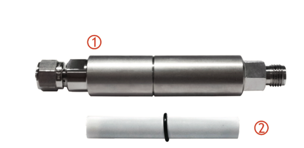
Figure 1. The Glycosorb heavy hydrocarbon and glycol filter. 1: filter assembly; 2: carbon cartridge.
In order to remove light hydrocarbon vapors (the propane/butane groups) from oil associated gas, Vympel engineers developed an oil type filter. This consists of a bubbler flask filled with special purpose dehydrated transformer oil. Within the flask is a gas distributor that causes the incoming gas to form evenly distributed bubbles as it passes into the oil (Figure 2). Filtration occurs through the absorption by the oil of C3 and C4 hydrocarbons.
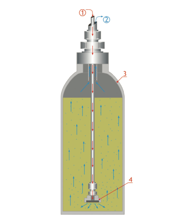
Figure 2. Oil type filter for light hydrocarbons.
1: gas inlet; 2: gas outlet; 3: bubble chamber; 4: gas distributor.
The operating principle is surprisingly straightforward, yet, after filtration, the resulting gas sample still has the same humidity, even while most of the early condensing hydrocarbons have been removed. This then allows the water to condense first so the WDP is easy to measure.
Measuring WDP downstream of glycol dehydration equipment
In order to provide a comprehensive automated solution for a gas treatment complex, it is necessary to ensure reliable measurement of gas moisture content. Yet, the main impediments to the full automation of natural gas treatment processes, in the context of a multiple component gas, are issues relating to the reliability of the equipment measuring humidity.
Continuous reliable measurement of the WDP immediately downstream of the glycol dehydration unit has remained a dilemma until quite recently. The use of automatic dew point transducers, at this point in the system, has been limited by the necessity to perform frequent preventive maintenance. In addition, analyser readings have often been unreliable due to the impact of condensing glycol vapors, and could not always be confirmed using manual/visual equipment.
The main problem in moisture measurement downstream of the glycol absorber is the glycol fog produced at the absorber outlet. This fog passes through the gas treatment system’s filtration device and enters the dew point analyser’s measurement chamber. As a rule, membrane filters are applied in gas treatment systems, but glycol droplets are small enough to mostly pass through this type of filter. The accumulation of glycol fog in the measuring chamber leads to distortion and increased instability in measurement results. The presence of this fog also accelerates the degradation of the analyser’s measuring cell.
Vympel’s solution to this problem is elegant yet simple: an inertial-gravitational filter (IGF) (Figure 3) that efficiently removes dispersed aerosols and solid phase contaminants from natural gas without any distortion of the gas sample.
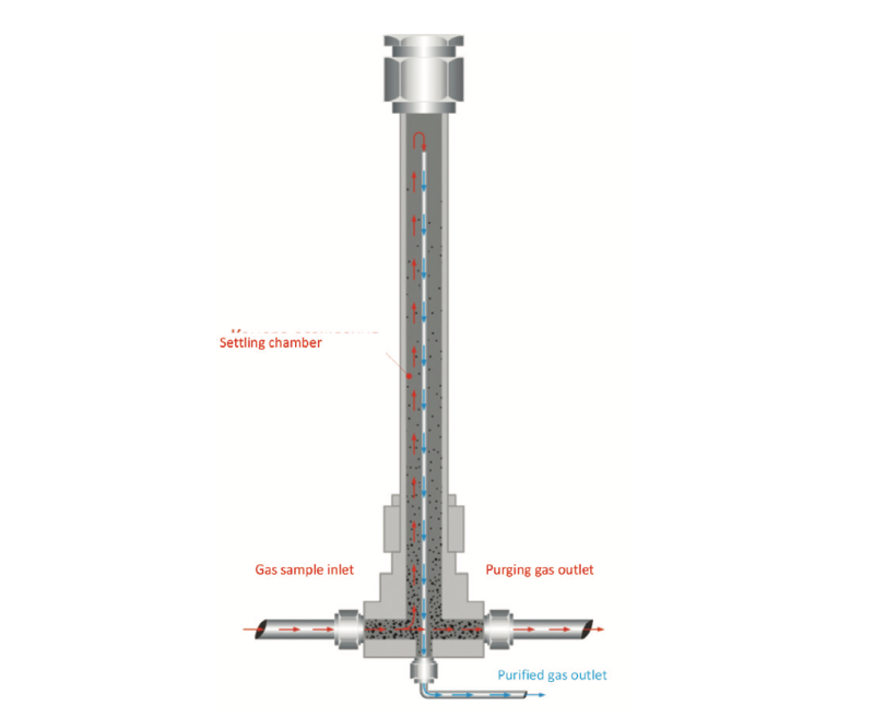
Figure 3. Inertial-gravitational filter (IGF).
As the name implies, the IGF has two filtering stages. In the inertial stage, the gas undergoes a rapid change in the direction of flow. The inertia of the solids and liquid phase impurities carries them out through the purge outlet. The density of most aerosols is, likewise, much greater than that of the gas, so the aerosols also separate from the gas after the change in flow direction and are eliminated.
The gravitational filtering section consists of a tubular vertical flow settling chamber surrounding a thin outlet tube. The inertially purified gas takes about five minutes to fill the settling chamber. When the gas reaches the open end of the outlet tube it flows down out of the filter to the analyser. The rate at which the gas fills the outer tube is slower than the settling velocity of any remaining particles and aerosols. As a result, gravity acting on these contaminants causes them to precipitate out of the gas where they are swept out by the purging gas flow.
Thanks to a design that features an absence of solid state mechanical or diaphragm filtering elements, the IGF does not require cleaning or regular replacement. It is a simple and efficient, yet very inexpensive, solution.
An example of how the IGF is incorporated into a complete gas preparation system can be seen in Figure 4. In this case, the IGF is a part of Vympel’s SGA-003 gas treatment system. The SGA-003 system was specially designed for CONG-Prima series analysers.
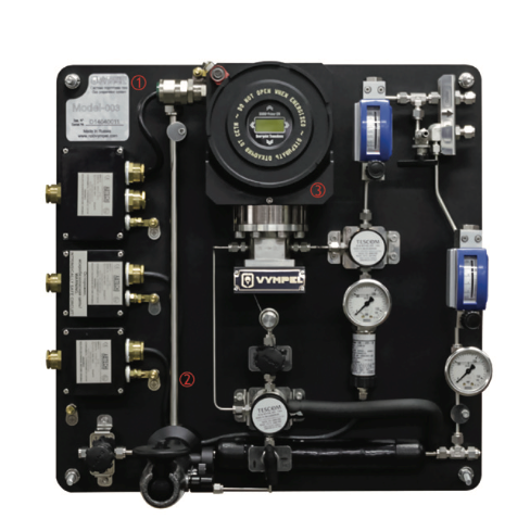
Figure 4. SGA-003 Gas Treatment System. 1: SGA-003 gas treatment system panel; 2: inertial-gravitational filter; 3: dew point transducer CONG-Prima-2M.
The following are the results of filtering elements tests performed in laboratories and at an operating gas plant.
Mobile filtering complex
In order to provide a comprehensive yet easily portable solution for the removal of heavy and light hydrocarbons and glycols from gas samples, Vympel engineers designed the MFK-1 mobile filtering complex. This consists of an oil type filter, Glycosorb filter, and gas sample supply and removal device (Figure 5).
The MFK-1 was tested in Vympel’s in-house laboratory. The objective of the tests was to evaluate how efficiently propane-butane group hydrocarbons were removed from the gas, and assess the impact of the MFK-1’s filtration on the WDP value. For the tests, Vympel’s reference standard device (VYMPEL-ED 300) created a gas condition with WDP temperatures in the range of -20 °C to -10 °C, and a hydrocarbon condensation temperature in the range of +5 °C to +10 °C. The Vympel ED-300 used a petroleum ether to reproduce a HCT for the propane-butane group HCs.
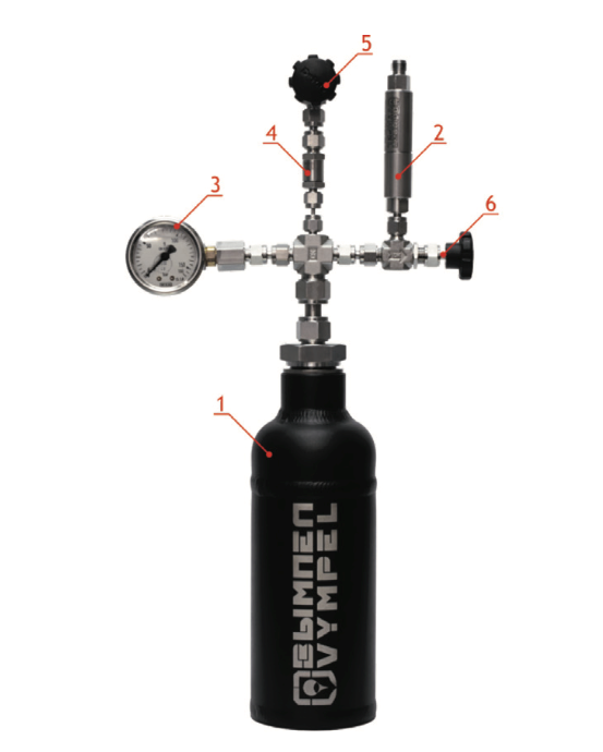
Figure 5. MFK-01 Mobile Filtering Complex.
1: oil filter; 2: Glycosorb filter; 3: pressure gauge; 4:back‐pressure valve; 5: inlet tap; 6: outlet tap.
After the gas flow has been saturated with the proper ratios of water and hydrocarbons, the gas is passed through the MFK-1. Hygrovision-mini manual dew point hygrometers were installed upstream and downstream of the MFK-1. The Hygrovision-mini analyser installed upstream of the MFK-1 was used for establishing the hydrocarbon condensation temperature of the unfiltered gas. The Hygrovision-mini analyser installed downstream of the MFK-1 validated the WDP created by the VYMPEL-ED 300 reference standard device.
Inertial-gravitational filtering at a gas treatment plant
The efficiency of the IGF’s performance was demonstrated during pilot tests at the OJSC Severneftegazprom gas field in Russia. The IGF was part of an SGA-003 gas treatment system outfitted with a CONG-Prima-2M. This system was installed on a process line immediately downstream of a glycol absorber. A Hygrovision-mini manual analyser was used as a monitoring/control instrument.
Over the course of the testing period (six months), several changes were made to the settings of the absorber, including changes in the glycol flow rate from 400 to 700 kg/hr. These flow rate changes were made in order to change the concentration of the glycol fog at the absorber outlet. The average pressure in the absorber was 70 bar. The IGF was the only filtering element in this system.
Figure 6 is a diagram of the results registered by the CP2M (the blue line). The readings of the Hygrovision-mini analyser are shown as red triangles. This graph illustrates the effectiveness of the IGF in removing glycol contamination before the gas sample is delivered to the automatic analyser.
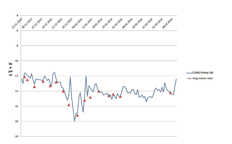
Figure 6. Dew point measurements made by a CONG-Prima-2M downstream of the glycol dehydration equipment.
Conclusion
In response to specific challenges confronting operators in the natural gas industry, Vympel engineers have successfully developed new filtration systems to ensure accurate and reliable analysis. With the introduction of these new filtering technologies – for online applications, the IGF, or inertial-gravitation filter for removing contaminants, including glycols associated with dehydration equipment, and for the portable applications the Glycosorb filter, oil-type filter and MFK-1 mobile filtering complex for dealing with gases rich in heavy hydrocarbons – several difficult issues inherent in gas sample preparation for analytical measurements have been solved more effectively, and in much greater scope, than before.
With specific reference to the problem of metering moisture in natural gas from gas condensate fields, the challenge of taking accurate manual and visual measurements has been solved thanks to the MFK-1. The next task is to design and develop an equally effective fixed-flow filtering complex that will allow for accurate and reliable humidity measurements of these gases using online automated analysers such as the CP2M.
Note
The tests were conducted using a secondary reference standard of dew point and hydrocarbon condensation temperature. The VYMPEL-ED 300 secondary reference standard supports simulation of DPT and HCT at an operating pressure below
30 MPa within the range of -80 °C to +30 °C.
Acknowledgement
S. V. Seleznev, G. A. Derevyagin and I. N. Moskalyov, SPA Vympel, Russia, were also contributing authors on this article.
References:
1. VYSHIVANYI, I. G., KOSTYUKOV, V. Y., MOSKALEV, I. N. and KUZNETSOV, S. A., ‘Condensation Hydgormeters: Condition and Improvement Prospects’, Automation, Telemechanization and Communication in Oil Industry, 2007, No. 7, pp. 2 - 12; No. 8, pp. 8 - 18.
2. MOSKALEV, I. N., ‘Natural Gas Humidity Metering: Condition and Problems’, MOSKALEV, I. N., BITYUKOV, V. S., FILONENKO, A. S., et al., Moscow: IRC Gazprom, 1999, p. 36.
3. MOSKALEV, I. N., ‘Natural Gas Humidity Metering: Problem view and tasks’, Gas Industry, 2000, No. 12, pp. 36 ‐ 38.
4. MOSKALEV, I. N., ‘Microwave Analysis of Natural Gas and Condensate, Vol. II’, MOSKALEV, I. N. and KOSTYUKOV, V. E., 'Sarov: The publishing and printing complex', FGUP RFYC-VNIIEF, 2014, p. 428.
