
Linear
telemechanics system
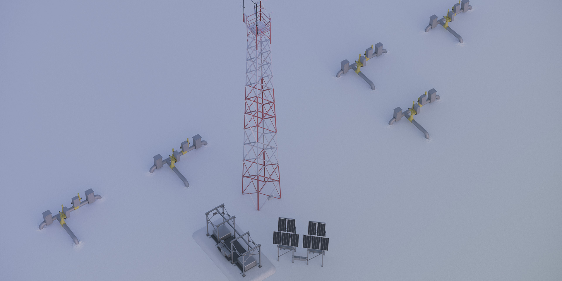
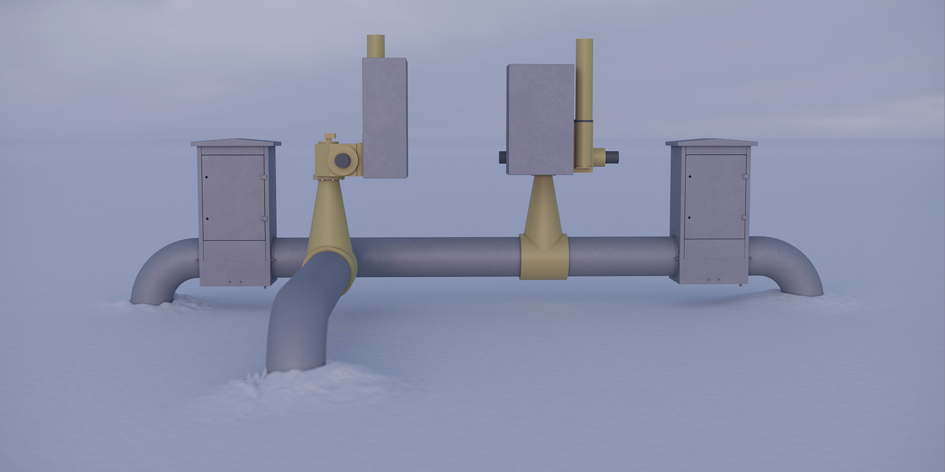
The pipeline linear telemechanics system (PLTM) is designed to ensure the safe transportation of liquid hydrocarbons by means of continuous monitoring of the piping system parameters and control of the pipeline actuators, detection of possible leaks for quick cut-off of emergency areas, control over routine operations for pipeline cleaning and diagnostics, control of the cathode protection system, power supply to the telemechanics units and connected equipment controlled by the system.
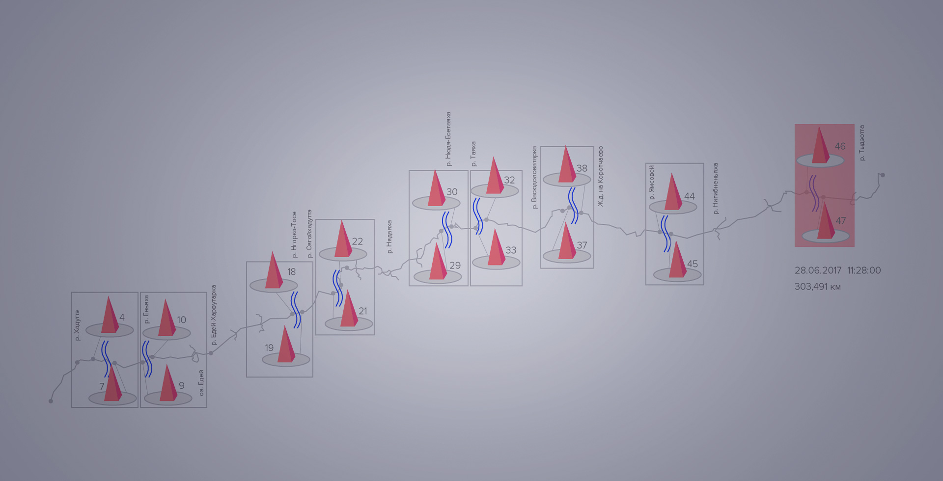
SLTM has two levels: upper level – control point (PU); lower level – controlled points (CPs) distributed along the length of the pipeline and the base controlled points (BCPs).
Wireless communication between the components of the SLTM is via VHF-band radio signal between the CP and the BCP and radio relay communications between the BCP and the PU. CPs and the BCPs are equipped with individual radio transceivers.
Power for control points can be supplied by an external power supply and/or Vympel’s proprietary autonomous power complex (APC), which uses renewable energy sources and is a part of the CP.
Use of the PLTM at production sites not connected to power grid is possible due to the ultra-low power consumption of all system components that have been developed by SPA Vympel.
Main functions:
- automatic collection, archiving, and transmission of data regarding the parameters of the medium transported in the underground product pipeline;
- electrochemical protection of the pipeline (ECP);
- leak detection of transported medium(LDS);
- control of the profression of the diagnostic and cleaning equipment (DAC);
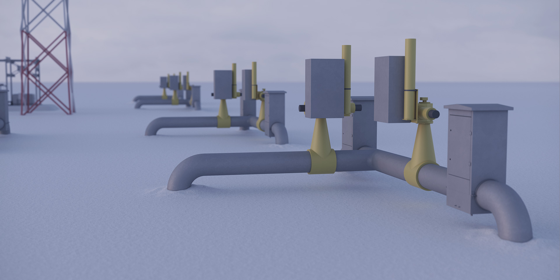
- control of actuators (ball valves);
- gas contamination control (GCC)
- security alarm;
- supply power for the pipeline’s technological equipment with or without access to an external power supply.
Fields of application
- Condensate pipelines
- Gas pipelines
- Oil pipelines
Signature
features
Reducing capital construction costs
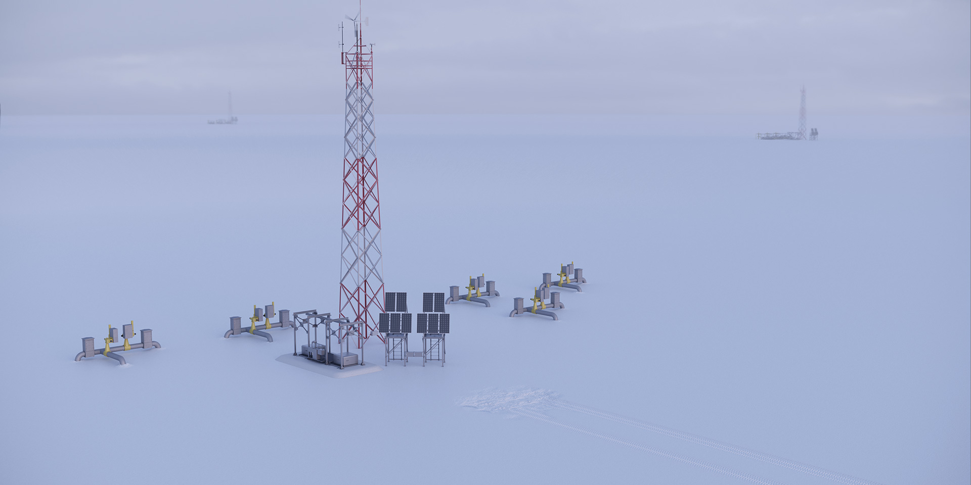
Power supply for operation of controlled points using renewable energy sources (wind and solar energy), resulting in a significant reduction in the facility’s capital construction costs (no power lines).
No electricity costs
Operation at extremely low ambient air temperatures (from -60 °C) in the Far North powered by onsite renewable sources thanks to the ultra-low power consumption of all SLTM components. As a result, energy costs, including heating, are greatly reduced.
Operation at high ambient air temperatures
Operation at high ambient temperature (up to +50 °C) in tropical conditions without air conditioning systems thanks to the ultra low heat emission of system components.
Unmanned maintenance technologies
Due to high system reliability and an advanced diagnostic system for monitoring the condition of the equipment, the SLTM is practically maintenance free.
Communication via wireless radio link
Automated digital communication between the upper and lower levels is carried out via wireless radio communication.

Remote control of the line valve
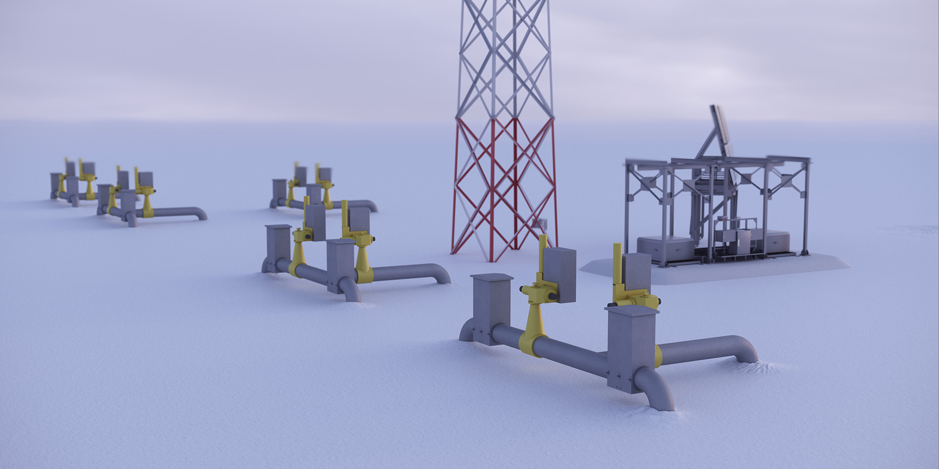
Remote control of the line valve by means of an electro-pneumatic control unit powered by the solar module; diagnostics analysis of the valve unit’s technological parameters; and continuous 24-hour operation.
Characteristics
The LV ICS components (except for the control room equipment, base controlled points, and equipment located in the underground modules) can function in an environment with the following parameters:
ambient temperatures from -60 °C to +50 °C; relative humidity up to 95% at 35 °C as long as there is no moisture condensation
The LV ICS provides data transfer from each controlled point to the control panel
The LV ICS base controlled point gathers data from the nearest controlled points via VHF radio.
The connection between the base controlled point and the subordinated controlled points is provided by
VHF radio modems
show all Characteristics
Principle of operation:
The LV ICS is a system for gathering processing, presenting and storing technological information about the parameters of the transported medium environment and the condition of pipelines.
Configuration*
show package contents
show package contents
Product order
Contact us
Leak detection system
Your cart
