
Vympel-80000
Grade 1 gas volume flow rate standard in value range of 800...80000 m3/h
The grade 1 gas volume flow rate standard is designed for reproduction of volume flow rate units in a range of 800-80000m3,
communicating their size to measuring instruments (flow meters), and R&D in their metrological supply.
The Vympel-80000 standard is bound to the Russian National Primary Flow Unit Standard. The standard has an error limit of 0.3% and allows for calibration and verification of flow meters with form factors Du600-Du1400 with an error limit of 0.5%. The operating environment used is air under standard conditions.
Signature
features
Accuracy rating A in the full flow range
Vympel-80000 is the only gas volume flow rate
standard that allows for verification of Du1400
ultrasonic flow meters with accuracy rating A
in the full flow range.
standard that allows for verification of Du1400
ultrasonic flow meters with accuracy rating A
in the full flow range.
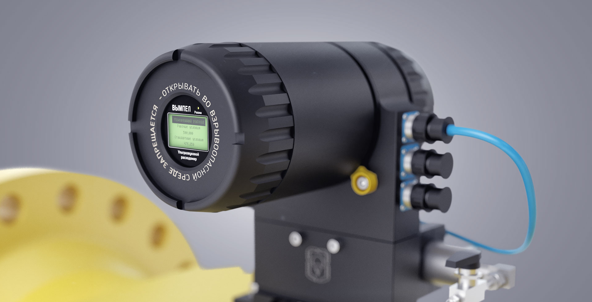
Reference measuring instrument: Vympel-500
Reference measuring instruments used are four 8-channel
ultrasonic flow meters Vympel-500 with an error limit of 0.2%
and form factors Du500.
ultrasonic flow meters Vympel-500 with an error limit of 0.2%
and form factors Du500.
High stability of set flows
High stability of set flows is ensured with a high volume receiver
User-friendly interface
Software with user-friendly interface allows for fully automated verification procedure
Characteristics
Flow range
800-80000 m3
Error limit
0,3%
Operating environment
air
HIDE ALL CHARACTERISTICS
Operation principle:
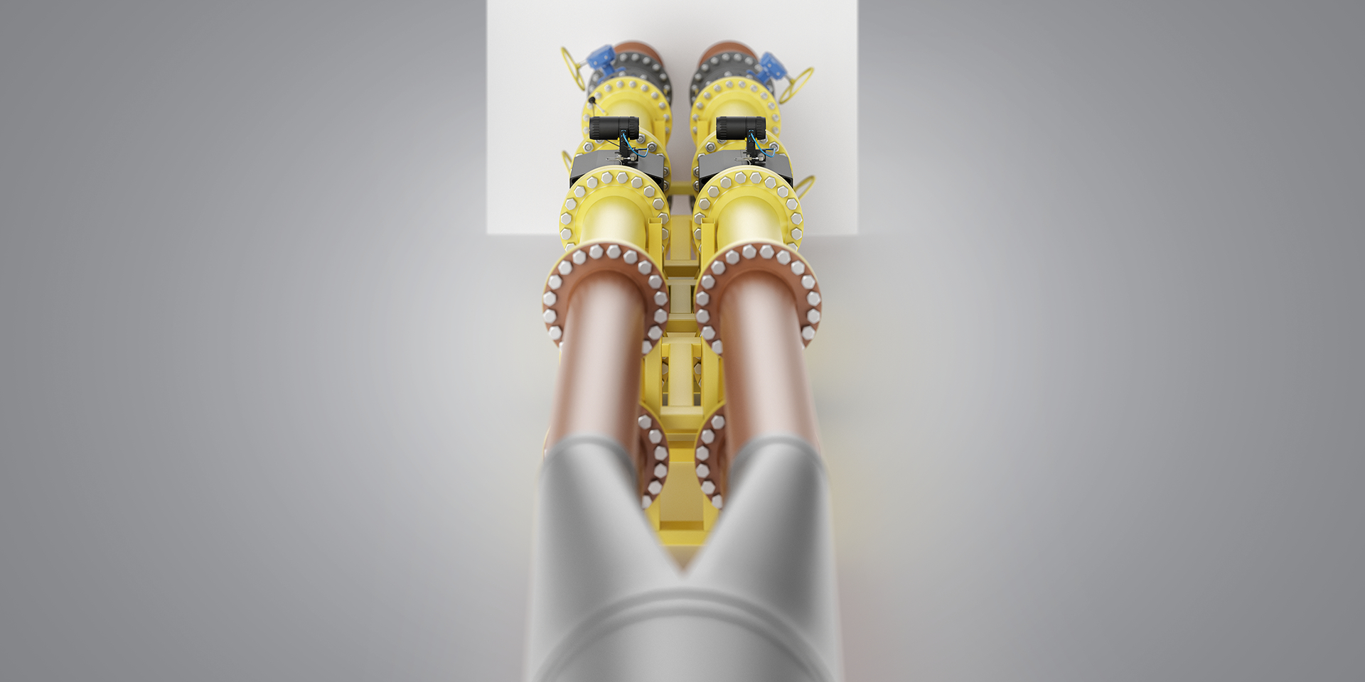
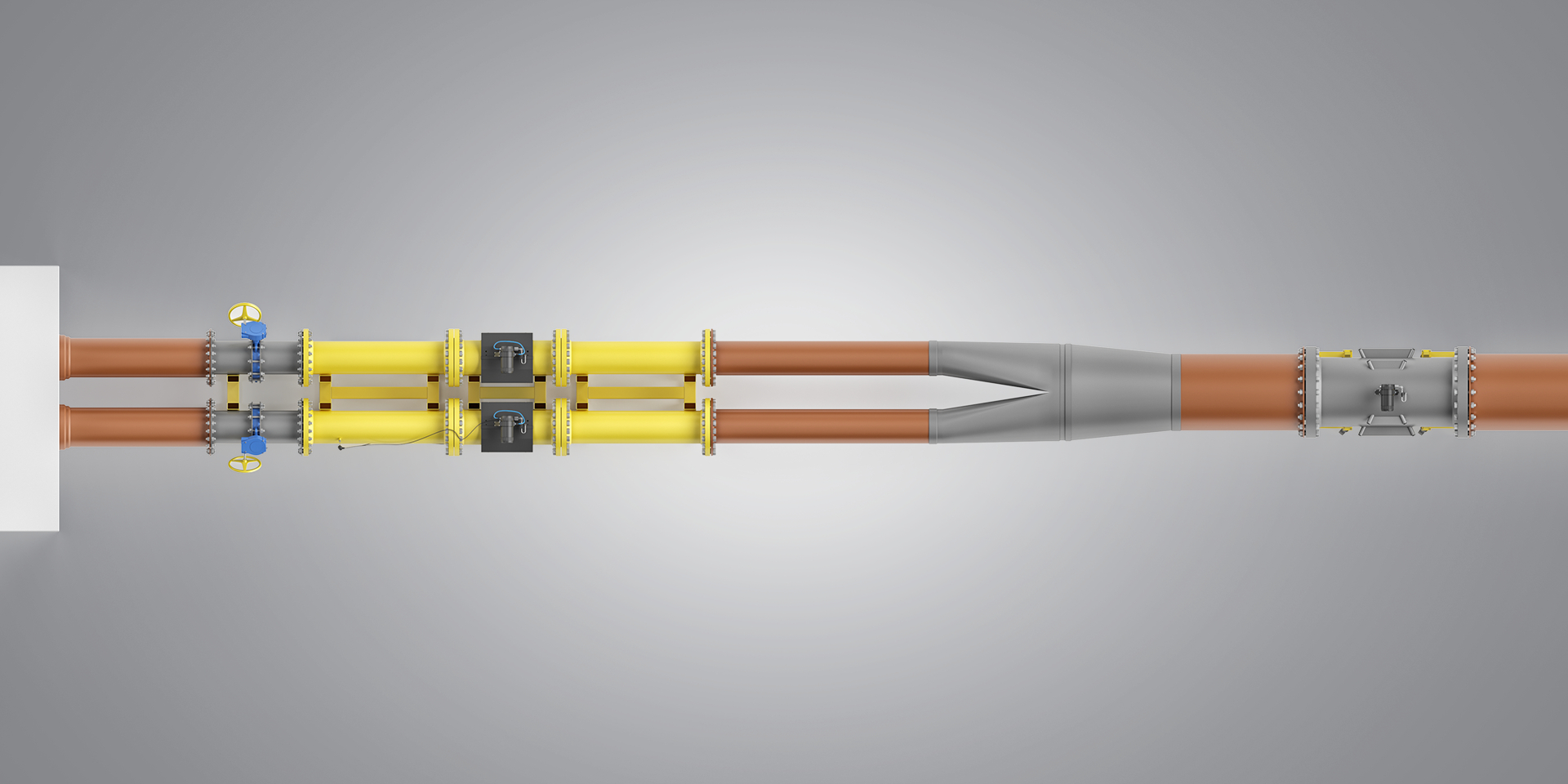
The installation includes the following units and parts (see figure):
- testing section (pos.1 – input straight section, pos.2 – output straight section, pos.3 – adapters);
- measuring section (pos.4, 5 input straight sections with flow straighteners DN 500 – 4pcs., pos.5 DN 500 – 4 pcs., pos.6 output straight sections DN 500 – 4 pcs.);
- pos.7 receiver and flow generator;
- pos.8 reference flow meter unit (4 pcs.);
- pos.9 verified flow meter;
- butterfly valves (4 pcs.) are builti in the output straight sections pos.6;
- set of measuring instruments and auxiliary equipment.
- power supply cabinet;
- operator workplace based on a controlling PC (process computer) with special software.

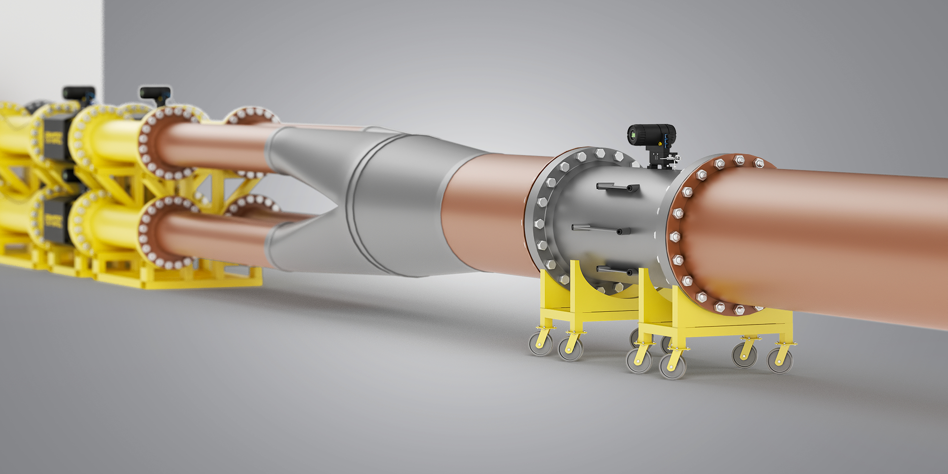
Testing section
The testing section consists of the verified instrument installation spot, a set of adapters and straight sections equipped with outlets for air flow parameter measuring sensors.
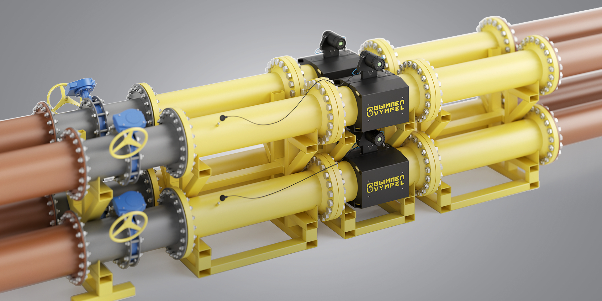
Measuring section
The measuring section includes four measuring lines (wires) mounted in parallel, with reference meters (ultrasonic flow meters) on each of them.
Every reference meter is a flange measuring section with piezoelectric sensors (16 pcs.) and pressure sensor, the measured medium temperature sensor is installed in the output straight section.
The reference meter electronic units have a flow metering channel, temperature metering channel, pressure metering channel, and provide data output on operating flow and flow converted to standard conditions.
The measuring lines (wires) are placed between the adapter and the receiver, damping the verification medium flow parameters.
Receiver
The receiver is rectangular in shape for easy mounting and dismounting of reference meters, it can be moved with ROCLA type manual cars, forklifts, overhead cranes, etc.
Instrument set and auxiliary equipment
The instrument and auxiliary equipment set is designed for monitoring and measuring the verification medium parameters during verification.
The instruments include:
- flow difference sensors ДП-19 КРАУ5.183.019-17 installed on each measuring line, connected to the reference meters and verified flow meter;
- pressure and pressure difference sensor programming devices КРАУ5.139.011;
The auxiliary equipment includes a set of information and power cables and a set of plugs.
Flow generator
The flow generator is based on type RH560/2 37 kW three-phase centrifugal fans (4 pcs.) with variable speed drives VACON0100-3L-0072-5-FLOW (4 pcs.) for smooth adjustment of fan rate and setting necessary head-capacity curve from the PC operator workplace.
Power supply cabinet
The power supply cabinet supplies power to the equipment, including the variable speed drives in the flow generator.
PC operator workplace and software
The PC operator workplace with special software for control and setting the installation operation parameters, gathering data from the verified and reference flow meters and auxiliary equipment, processing and storage of data and reporting is placed near the installation.
Software
The software of the hardware support installation is autonomous (PC-based software). The verified measuring instruments are connected through closed communication channels. The measured units are converted and measurement data is processed using the internal hardware and software. The software and gathered data are stored in the internal storage device (PC hard disk drive). The software environment is constant, there are no means or user shell for programming or modification of software.
The installation's software is designed for gathering, processing and presenting information on verification. The software allows for:
- automatic or manual verification;
- saving intermediate and final results of verification in the database;
- exporting the verification results in the verification report format;
- loading the verification or study results from the database with the flow meter serial number;
- automaic identification and entering the calibration factors in the verified flow meters.
The software for the installation is divided into:
- metrologically significant part;
- metrologically non-significant part;
The metrologically significant software includes:
- software modules involved in processing (calculation) of the measurement results or affecting them;
- software modules involved in gathering or presenting measurement information, its storage, transfer, identification, protection of software and data;
- software parameters involved in calculations and affecting measurement results;
The metrologically insignificant software includes the software graphic user interface.
The software is identified based on the digital signature of the archive containing the executed code.
The digital signature algorithm is MD5 with RSA.
Installation operation mode
The installation operation modes are set with the stand automation control program controlling the flow generator fans.
Product order
Contact us
VYMPEL-500
Multibeam ultrasonic measuring system
Your cart
